What Is a Wire-to-Board Connector?
A wire-to-board (WTB) connector is an interface that connects a discrete wire or cable to a printed circuit board (PCB). It consists of a crimp housing (on the wire side) and a header or pin header (soldered to the PCB). These connectors are widely used in consumer electronics, automotive systems, industrial automation, and medical devices where modular wiring is essential for assembly, maintenance, and repair.
Key Selection Parameters
1. Pitch
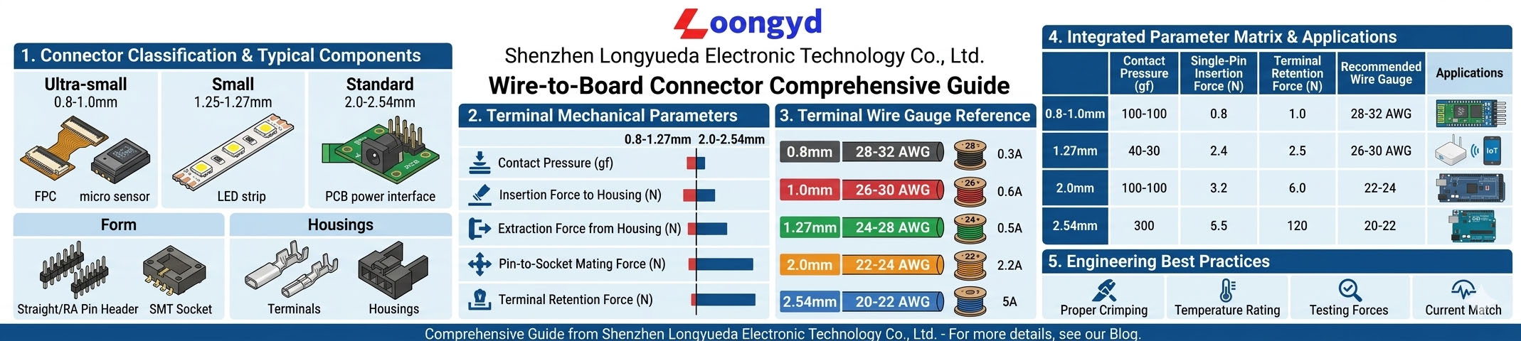
Pitch is the center-to-center distance between adjacent pins. It determines the connector’s size and current capacity:
- 1.0 mm – 1.25 mm pitch: Ultra-compact designs for smartphones, wearables, and miniaturized PCBs. Lower current (1–3A).
- 1.5 mm – 2.0 mm pitch: Mid-range connectors for consumer electronics, home appliances, and small sensors (3–5A).
- 2.5 mm – 2.54 mm pitch: Standard industrial and automotive connectors. Good balance of size, current, and durability (5–10A).
- 3.0 mm+ pitch: High-power applications requiring larger wire gauges. Used in power supplies, battery packs, and heavy machinery.
2. Mechanical Specs
Key mechanical parameters to consider:
- Insertion Force: Determines ease of mating and unmating. For multi-pin connectors, low insertion force (LIF) or zero insertion force (ZIF) designs reduce operator fatigue.
- Durability (Mating Cycles): Most WTB connectors are rated for 50–1,000+ cycles. Choose higher cycle ratings for applications requiring repeated disconnection.
- Locking Mechanism: Friction lock, positive lock, or secondary lock depending on vibration levels in the operating environment.
- Mounting Orientation: Right-angle or vertical headers determine PCB layout flexibility.
3. AWG Wire Gauge Matching
Proper AWG matching ensures reliable crimping and current-carrying capacity:
| Pitch Range | Compatible AWG | Typical Current | Common Applications |
|---|---|---|---|
| 1.0 – 1.25 mm | 28 – 32 AWG | 1 – 3A | Mobile devices, wearables |
| 1.5 – 2.0 mm | 24 – 28 AWG | 3 – 5A | Home appliances, sensors |
| 2.5 – 2.54 mm | 20 – 26 AWG | 5 – 10A | Automotive, industrial control |
| 3.0+ mm | 16 – 22 AWG | 10 – 20A+ | Power supplies, battery packs |
Pitch-Specific Product Recommendations
Longyueda offers a complete range of wire-to-board SMT connectors to match your pitch requirements:
- 1.25 mm Pitch Wire-to-Board SMT Connector Series — Compact design for space-constrained PCBs, available in 2–15 positions.
- 1.5 mm Pitch Wire-to-Board SMT Connectors — Mid-range option balancing size and reliability.
- 1.8 mm Pitch Wire-to-Board SMT Connector Series — Ideal for home appliances and industrial sensors.
- 2.0 mm Pitch Wire-to-Board Connector Series — Popular choice for general-purpose industrial and consumer electronics.
- 2.5 mm Pitch SMT Wire-to-Board Connector — Higher current capacity for automotive and power applications.
- 2510 2.54 mm Pitch Wire-to-Board Connector — Industry-standard 2.54 mm pitch for breadboard-compatible designs.
Common Wire-to-Board Connector Types
| Type | Pitch | Locking | Features |
|---|---|---|---|
| Simple Header + Housing | 1.0 – 2.54 mm | Friction / Positive | Basic, cost-effective, widely used |
| Pico-Lock / Micro-Lock | 1.0 – 1.5 mm | Positive lock | Secure retention, compact size, vibration resistant |
| ZIF / LIF Connectors | 0.5 – 1.0 mm | Sliding actuator | Zero insertion force for flex cables & high-density needs |
| Blade Battery Connectors | 1.5 – 2.0 mm | Snap-lock | High-current battery applications, low profile |
How to Select the Right Wire-to-Board Connector
- Determine current requirements. Check both steady-state and peak current for each pin.
- Select pitch based on PCB space. Smaller pitch saves space but requires tighter manufacturing tolerances.
- Match AWG to terminal specifications. Use the AWG – Pitch chart above as a starting point.
- Check environmental conditions. Temperature range, humidity, and vibration level influence housing material and locking mechanism choice.
- Verify mating cycle requirements. Higher cycles require gold-plated contacts and robust terminal design.
- Confirm assembly process. SMT reflow-compatible headers reduce manufacturing steps.
Frequently Asked Questions
What is the difference between wire-to-board and board-to-board connectors?
Wire-to-board connectors connect a discrete wire or cable to a PCB, enabling modular wiring for assembly and repair. Board-to-board connectors directly connect two PCBs without cables, typically for stacking or parallel connections. WTB connectors are more flexible for cable routing, while BTB connectors are more compact for direct board stacking.
How do I choose the right pitch for my wire-to-board connector?
Choose pitch based on current requirements and available PCB space. Smaller pitches (1.0–1.25 mm) suit low-current compact designs. Standard pitches (2.0–2.54 mm) work for most industrial applications. Larger pitches (3.0+ mm) are needed for high-current power connections.
What AWG wire should I use with a 2.54 mm pitch connector?
A 2.54 mm pitch wire-to-board connector typically accepts 20–26 AWG wire, with the most common sizes being 22–24 AWG for general-purpose applications. Always check the terminal manufacturer’s specifications for the exact wire range.
What is the typical current rating for a wire-to-board connector?
Current ratings vary by pitch and terminal design. Typical ratings range from 1–3A for 1.0–1.25 mm pitch connectors up to 10–20A for 3.0+ mm pitch connectors. Always derate to 80% of the rated current for continuous operation in elevated temperature environments.
Can I mix different AWG wires in the same connector?
Yes, as long as each wire falls within the terminal’s specified AWG range. Use terminals designed for each wire size. Some multi-row connectors accommodate different AWG sizes in different positions. Contact Longyueda for custom terminal-to-wire matching support.
Conclusion: Make the Right Connection
Selecting the correct wire-to-board connector directly affects your product’s reliability, manufacturability, and cost. By understanding pitch, mechanical specifications, and AWG matching, you can make informed decisions that improve assembly yields and long-term performance.
With over 20 years of connector manufacturing experience, Shenzhen Longyueda Electronic Technology offers a wide range of wire-to-board SMT connectors from 1.0 mm to 2.54 mm pitch to suit every application.
🔧 Download Wire-to-Board Connector Guide & Request Samples →
For more connector selection guidance, see our board-to-board connector selection guide and industrial RJ45 connector reliability guide.
Related: 5.08mm Pluggable Terminal Block System — Screw cage 300V 10A, 2-24P, Phoenix MSTB 2.5 compatible.
Explore More: DIN Rail Pluggable Terminal Block Header 5.08mm — 5.08mm DIN rail pluggable terminal block headers, 300V 15A, PA66 UL94 V-0. Compatible with 35mm and 15mm DIN rail systems.
