SMT Connector: The Complete Guide to Surface Mount Connectors for PCB Design
By Nick / June 9, 2026
Introduction: What Is an SMT Connector?
A Surface Mount Technology (SMT) connector is an electronic interconnect component designed to be soldered directly onto the surface of a printed circuit board (PCB), rather than inserted through drilled holes as with traditional through-hole technology. SMT connectors have become the dominant interconnection solution in modern electronics manufacturing, enabling higher component density, improved electrical performance, and cost-effective automated assembly.
From compact consumer devices to industrial control systems, electric vehicle battery management, and telecommunications infrastructure, SMT connectors serve as the critical interface between PCBs, cables, and system modules. Understanding SMT connector types, specifications, and selection criteria is essential for any engineer, designer, or procurement professional working in electronics manufacturing.
This comprehensive guide covers everything you need to know about SMT connectors — from fundamental technology principles and types to selection guidelines, assembly best practices, and application-specific considerations. Whether you are designing a new PCB layout or sourcing connectors for high-volume production, this guide provides the technical depth required to make informed decisions.
What Is Surface Mount Technology (SMT)?
Surface Mount Technology (SMT) is a method of assembling electronic circuits where components are mounted directly onto the surface of PCBs. Unlike through-hole technology (THT), which requires leads to pass through holes in the board, SMT components have small metal contacts or solder balls that are soldered directly to pads on the PCB surface.
Key Advantages of SMT Connectors Over Through-Hole
| Parameter | SMT Connector | Through-Hole Connector | Advantage |
|---|---|---|---|
| Component Density | High — both sides of PCB usable | Low — through-holes consume space | SMT: 60-80% space savings |
| Automated Assembly | Fully compatible with pick-and-place | Often requires manual or wave soldering | SMT: 3-5× faster production |
| High-Frequency Performance | Lower parasitic inductance/capacitance | Higher parasitics from long leads | SMT: Superior signal integrity |
| Weight | Lighter — no through-hole hardware | Heavier — larger body, longer pins | SMT: 40-60% lighter |
| Vibration Resistance | Excellent — low profile, rigid mount | Good but taller profile | SMT: Better for harsh environments |
| Cost (High Volume) | Lower — fewer process steps | Higher — multiple process steps | SMT: 20-40% cost reduction |
Common Types of SMT Connectors
SMT connectors come in a wide variety of configurations to serve different interconnection needs. Understanding these types is the first step in selecting the right connector for your application.
1. Board-to-Board (BTB) SMT Connectors
Board-to-board SMT connectors provide direct electrical and mechanical interconnection between two or more PCBs. They eliminate the need for cables or wire harnesses in many applications, making them ideal for compact stacked PCB designs.
Key Subtypes:
- Mezzanine Connectors — Parallel board stacking with controlled spacing (typically 5mm to 30mm board gap)
- Dual-Slot BTB Connectors — High-density interconnection with two rows of contacts, available in pitches from 0.4mm to 0.8mm
- Board-to-Board SMT Connectors — Standard parallel or perpendicular board mating options with pitch ranges from 0.5mm to 2.0mm
Typical Pitch Range: 0.4mm – 2.0mm
Typical Current Rating: 0.5A – 5.0A per contact
Common Applications: Smartphones, tablets, laptop motherboards, industrial control modules, EV battery management systems
Longyd offers a range of high-reliability board-to-board SMT connectors including 0.5mm dual-slot and 0.8mm dual-slot types for space-constrained designs. For a deeper technical dive, see our SMT Board-to-Board Connector Technology Guide.
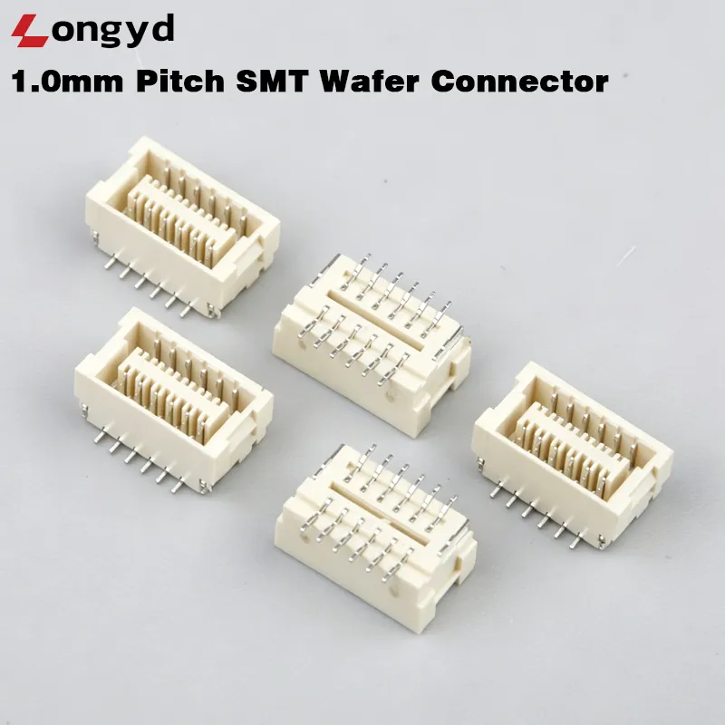
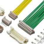
2. Wire-to-Board (WTB) SMT Connectors
Wire-to-board SMT connectors provide a detachable interface between discrete wires or cables and a PCB. They are among the most widely used connector types in electronics, valued for their versatility in power and signal distribution.
Key Subtypes:
- SMT Wafer Connectors — Low-profile right-angle or vertical headers with surface-mount tails
- Shrouded Headers — Protected mating interface for reliable connections in high-vibration environments
- SMT Female Headers — Surface-mount receptacles for board-to-wire bridging
Typical Pitch Range: 1.0mm – 2.54mm
Typical Current Rating: 1.0A – 5.0A per contact
Common Applications: LED lighting, home appliances, automotive interior electronics, industrial sensors
Longyd manufactures 12 different series of wire-to-board SMT connectors across pitches from 1.0mm to 2.54mm. For help with selection, see our Wire-to-Board Connector Selection Guide.
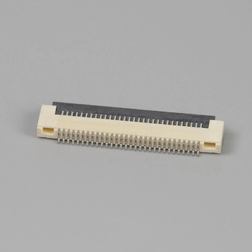
3. SMT FPC/FFC Connectors
Flexible Printed Circuit (FPC) and Flat Flexible Cable (FFC) SMT connectors provide zero-insertion-force (ZIF) or low-insertion-force (LIF) connections to flexible circuits. These connectors are essential in modern compact electronics where space is at a premium.
Typical Pitch Range: 0.3mm – 1.0mm
Typical Current Rating: 0.3A – 1.0A per contact
Common Applications: Camera modules, display panels, touch screens, portable devices
Explore Longyd’s 0.5mm pitch FPC connector for compact display and sensor applications.
4. SMT Power Connectors
Dedicated SMT power connectors are designed for higher current-carrying capacity, typically featuring reinforced contacts, wider pitch spacing, and enhanced thermal management features.
Typical Pitch Range: 2.0mm – 5.0mm
Typical Current Rating: 3.0A – 30A+ per contact
Common Applications: Battery packs, power supplies, motor drives, EV charging systems
5. SMT I/O Connectors
Input/output connectors in SMT format provide board-level interfaces for external connections. Common examples include USB-C receptacles, HDMI connectors, and RJ45 jacks in SMT packages.
Applications: USB-C side entry receptacles, HDMI-to-DVI adapters, RJ45 Ethernet connectors
For structured cabling and data center deployments, Cat 6A/6 Tool-less Keystone Jack (10Gbps, 500MHz, No Tools Required) offers tool-less Cat 6A termination with 50µ gold-plated contacts supporting 10Gbps over 100m channels.
Longyd offers USB-C 24-pin side entry SMT receptacles and industrial RJ45 connectors for demanding applications.
Key Technical Specifications for SMT Connector Selection
Selecting the correct SMT connector requires careful evaluation of several critical technical parameters. Below is a comprehensive reference table:
| Parameter | Typical Range | Selection Criteria | Industry Standards |
|---|---|---|---|
| Contact Pitch | 0.4mm – 2.54mm | PCB routing density vs. current requirement | IEC 61076-2, EIA 541 |
| Current Rating | 0.3A – 10A per contact | Power delivery needs, derating for temperature | UL 1977, IEC 60512 |
| Voltage Rating | 50V – 300V AC/DC | Safety margin, creepage distance | UL 1977, IEC 60950 |
| Contact Resistance | 10mΩ – 50mΩ max | Signal integrity, power loss | EIA 364-06, MIL-STD-1344 |
| Insulation Resistance | ≥1,000MΩ at 500VDC | Leakage current, isolation safety | IEC 60512-3, EIA 364-21 |
| Operating Temperature | -40°C to +105°C (standard) -55°C to +125°C (industrial) | Application environment, thermal cycling | AEC-Q200, IEC 60068 |
| Mating Cycles | 10 – 100+ cycles | Serviceability, field maintenance frequency | EIA 364-09, IEC 60512-9 |
| Mating Force | 0.5N – 3.0N per contact | User experience, insertion/extraction tooling | EIA 364-13, IEC 60512-13 |
| Durability Rating | 30 – 10,000 cycles | Expected device lifespan, maintenance schedule | EIA 364-09, USCAR-2 |
| Solder Joint Reliability | 500 – 2,000 thermal cycles | CTE mismatch, PCB material, solder alloy | JESD22-A104, IPC-9701 |
SMT Connector Material Systems
The performance and reliability of an SMT connector depend heavily on its material construction:
Contact Materials
| Material | Properties | Best For |
|---|---|---|
| Phosphor Bronze (C5191) | Good spring properties, moderate conductivity, cost-effective | Standard commercial applications |
| Beryllium Copper (C17200) | Excellent spring properties, high conductivity, high cost | High-reliability, high-cycle applications |
| Brass (C2680) | Good conductivity, low cost, poor spring properties | Fixed contacts, low-cycle applications |
Contact Plating
- Gold over Nickel — Best corrosion resistance, excellent conductivity, recommended for low-voltage / low-current signal applications
- Tin (Matte or Bright) — Cost-effective, good solderability, suitable for high-current power contacts
- Selective Gold Plating — Gold on mating surface, tin on solder tail — optimal balance of performance and cost
Housing Materials
| Material | Key Properties | Maximum Operating Temp | Applications |
|---|---|---|---|
| LCP (Liquid Crystal Polymer) | High-temperature resistance, excellent dimensional stability, low moisture absorption | 260°C – 280°C | Automotive, industrial, reflow-compatible designs |
| PA9T / High-Temperature Nylon | Good mechanical strength, high-temperature capability, moderate cost | 240°C – 260°C | Standard SMT applications |
| PPS (Polyphenylene Sulfide) | Excellent chemical resistance, high-temperature capability, stiff flow | 240°C – 260°C | Harsh chemical environments |
| PBT (Polybutylene Terephthalate) | Good mechanical properties, cost-effective, lower temperature resistance | 220°C – 240°C | Consumer electronics, low-cost applications |
SMT Connector Assembly Best Practices
PCB Land Pattern Design
Proper land pattern design is critical for reliable SMT connector soldering:
- Follow manufacturer-recommended pad dimensions and layout
- Ensure adequate solder mask clearance (0.05mm – 0.15mm around pads)
- Add thermal relief for large ground/power pads to prevent tombstoning
- Include fiducial marks for automated optical alignment
- Verify pad pitch matches connector terminal pitch within ±0.05mm tolerance
Solder Paste and Stencil Design
| Pitch Range | Recommended Stencil Thickness | Solder Paste Type |
|---|---|---|
| ≥1.0mm | 0.12mm – 0.15mm | Type 3 (25-45μm particle size) |
| 0.5mm – 1.0mm | 0.10mm – 0.12mm | Type 4 (20-38μm particle size) |
| 0.4mm – 0.5mm | 0.08mm – 0.10mm | Type 4 or Type 5 (10-25μm particle size) |
Reflow Soldering Profile
For LCP and high-temperature nylon SMT connector housings:
- Preheat / Ramp: 150°C to 180°C at 1-3°C/second
- Soak: 180°C to 217°C for 60-90 seconds
- Reflow: Peak temperature 240°C – 250°C, time above liquidous: 40-70 seconds
- Cooling: 2-4°C/second ramp down
Critical Warning: Do not exceed 260°C peak temperature for LCP housings, or 255°C for PBT housings, to avoid plastic deformation or melting.
Inspection and Quality Control
For high-reliability applications, implement these inspection methods:
- SPI (Solder Paste Inspection) — Verify paste volume, height, and alignment before component placement
- AOI (Automated Optical Inspection) — Post-reflow inspection for solder joint defects, bridging, and component alignment
- X-Ray Inspection — For hidden solder joints under connector bodies (fine-pitch and bottom-terminated connectors)
- Pull/Shear Testing — Destructive testing for process qualification and periodic verification
For detailed quality control processes, see our SMT Connector Quality Control Automation Guide.
SMT Connector Applications by Industry
Automotive & Electric Vehicles
SMT connectors in automotive and EV applications must meet stringent AEC-Q200 and USCAR-2 reliability standards. Typical applications include:
- Battery management system (BMS) board interconnections — 2.0mm pitch blade battery connectors
- ECU and ADAS module connectors
- Infotainment system board-to-board links
- LED lighting module interfaces
Industrial Automation & Robotics
Industrial environments demand connectors with high vibration resistance, extended temperature range, and robust mating cycles:
- Industrial control PCB stacking with industrial SMT connectors
- Robotic joint sensor interfaces
- Programmable logic controller (PLC) module interconnects
- HMI and display connections
Consumer Electronics
The consumer electronics industry drives much of the SMT connector innovation, particularly in miniaturization:
- Smartphone main board-to-sub board connections (0.4mm-0.5mm pitch)
- Tablet and laptop display-to-mainboard bridges
- Wearable device battery and sensor connections
- Camera module FPC connectors
Telecommunications & Data Centers
- Server backplane and daughter card connections
- Network switch PCB interconnects
- 5G base station module connectors
- Power shelf backplane connectors for rectifier systems
New Energy & Renewable Energy
- Solar inverter control board connectors
- Energy storage system (ESS) battery management interfaces
- EV charging station control modules
- High-performance battery connectors for energy storage
SMT Connector Selection Checklist
Use this checklist when evaluating SMT connectors for your next project:
- Define Electrical Requirements
- Voltage and current per contact
- Signal integrity requirements (frequency, impedance)
- Power vs. signal contact mix
- Determine Mechanical Constraints
- Board-to-board spacing (stack height)
- Mating axis (vertical, right-angle, or parallel)
- Available PCB real estate and component keep-out zones
- Evaluate Environmental Conditions
- Operating temperature range
- Vibration and shock levels
- Humidity, dust, and chemical exposure
- Assess Manufacturing Compatibility
- Reflow profile compatibility with connector housing material
- Pick-and-place compatibility (taped and reel packaging)
- Solder joint inspection accessibility
- Validate Reliability Requirements
- Required mating cycles
- Thermal cycling and temperature humidity testing
- Regulatory certifications (UL, RoHS, REACH)
- Review Supply Chain Considerations
- Lead times and MOQ requirements
- Multiple source compatibility
- Cost vs. performance trade-offs
Frequently Asked Questions
What is an SMT connector?
An SMT (Surface Mount Technology) connector is an electronic component designed to be soldered directly onto the surface of a PCB using automated pick-and-place and reflow soldering processes. Unlike through-hole connectors, SMT connectors do not require drilled holes for mounting.
What is the difference between SMT and SMD connectors?
SMD (Surface Mount Device) is the broader category for any component mounted using surface mount technology. SMT connectors are a subset of SMD components. In practice, the terms are often used interchangeably when referring to connectors.
What are the advantages of SMT connectors over through-hole?
SMT connectors offer higher component density (both sides of PCB usable), better high-frequency electrical performance (lower parasitic inductance), compatibility with automated assembly (faster, more consistent), reduced weight, and typically lower cost in high-volume production.
Can SMT connectors handle high current?
Yes. While standard SMT signal connectors typically handle 0.5A to 3A per contact, specialized SMT power connectors with reinforced contacts and optimized thermal management can handle 10A to 30A+ per contact. The 2.0mm pitch blade battery connector from Longyd is an example of a high-current SMT connector.
What pitch SMT connector should I use?
- 0.4mm – 0.5mm pitch: For ultra-high-density designs (smartphones, wearables)
- 0.5mm – 0.8mm pitch: For compact consumer and industrial electronics
- 1.0mm – 1.25mm pitch: Balance of density and reliability for general-purpose designs
- 1.5mm – 2.54mm pitch: For power applications and simplified routing
How do I ensure SMT connector solder joint reliability?
Follow manufacturer land pattern recommendations, optimize stencil design for proper paste volume, control reflow profile within specified limits, implement AOI inspection, and conduct thermal cycling validation per IPC-9701 or JESD22-A104 standards.
What is the typical lifespan of an SMT connector?
Connector lifespan depends on application conditions. Under normal operating conditions with proper design margins, SMT connectors can last the lifetime of the host device (10-20+ years). Key factors include thermal cycling frequency, vibration levels, humidity exposure, and number of mating cycles.
Conclusion
SMT connectors are fundamental building blocks of modern electronic systems, enabling the high-density, high-reliability interconnections that power everything from consumer wearables to industrial robots and electric vehicles. Understanding the technology types, material systems, specifications, and assembly best practices covered in this guide equips engineers and procurement professionals to make confident, informed selections.
As a specialized connector manufacturer with over 20 years of experience, Longyd offers a comprehensive range of SMT connectors — from wire-to-board and board-to-board types to FPC connectors and industrial power solutions — manufactured in ISO9001-certified facilities with UL, RoHS, and CE compliance.
Need help selecting the right SMT connector for your application? Contact our engineering team for technical support or request custom samples.
Longyd — Your trusted custom connector and wire harness manufacturer since 2004. ISO9001 certified, UL compliant, globally delivered.