

Proper installation of high-current IP67 terminal posts directly determines whether you achieve the rated electrical performance and environmental protection. Follow this IP67 terminal post installation guide carefully — even the best-designed connector will fail prematurely if you install it incorrectly. This guide walks you through every key installation step for LYD’s rectangular terminal post series, including 120A, 150A, 200A, 300A, and 400A models.
Whether you work on battery energy storage systems, electric vehicles, or marine power distribution, following this IP67 terminal post installation guide ensures you get reliable performance and a watertight seal every time. For additional waterproof connection solutions, explore our full range of IP67 waterproof connectors or check out the IP67 waterproof M12 PCB mount connector for lower-current applications.
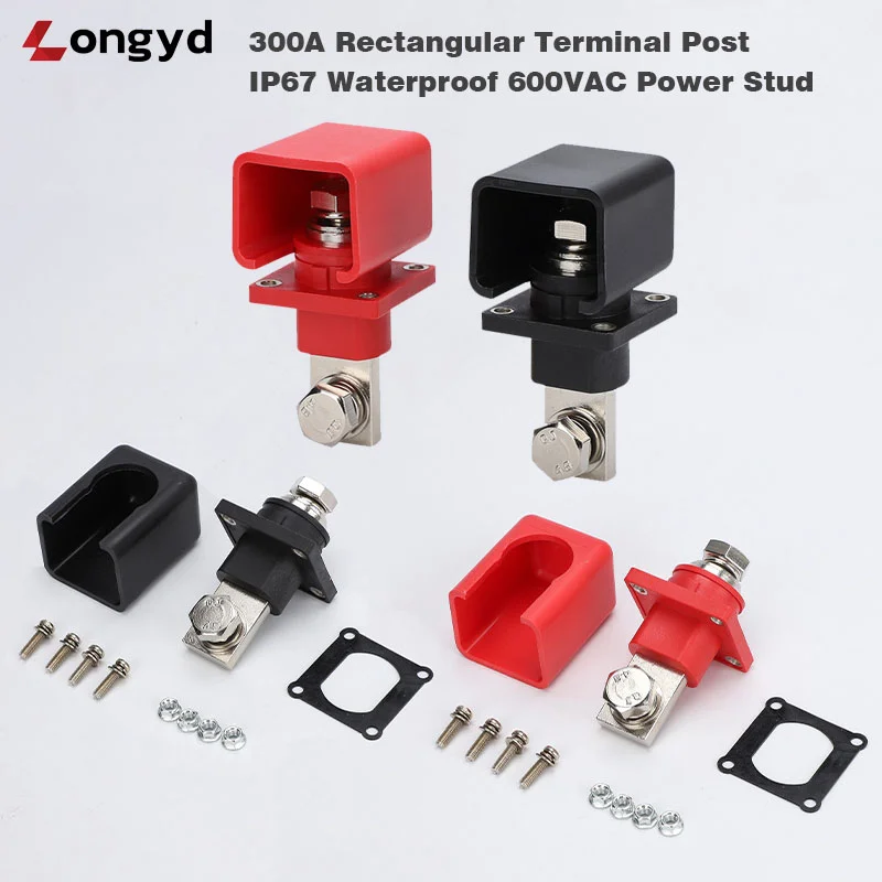
Tools You Need for IP67 Terminal Post Installation
First, gather the correct tools before you start. Using the wrong tool often leads to seal failure or poor electrical contact.
- Torque wrench capable of 2–8 Nm range (calibrated recommended)
- Hex key or socket for mounting nuts
- Wire stripper for C-Type cable lug connections
- Crimping tool — hydraulic tool recommended for cables 50 mm² and above
- Deburring tool for smoothing panel cutout edges
Step 1: Prepare the Panel Cutout for IP67 Terminal Post Installation
Start by drilling or punching a clean rectangular or square hole according to the dimensional drawing supplied with your terminal post. A precise cutout matters because it directly affects the O-ring seal.
- Drill or punch a clean rectangular or square hole per the dimensional drawing provided with your terminal post.
- Deburr all edges to prevent damage to the silicone O-ring during installation.
- Ensure the panel material is clean, dry, and free of oil or grease.
Tip: A rough cutout edge can compromise the IP67 seal. Therefore, use a file or deburring tool to smooth all sharp edges. IEC 60529 defines the IP67 ingress protection standard, and even minor seal damage can let water enter the enclosure.
Step 2: Position the O-Ring — IP67 Terminal Post Installation Guide
The silicone O-ring comes pre-installed in the groove on the underside of the terminal post flange. However, you should always verify its condition before mounting.
- The silicone O-ring is pre-installed in the groove on the underside of the terminal post flange.
- Verify the O-ring is seated evenly with no visible twists or gaps.
- Insert the terminal post through the panel cutout from the outside.
While the O-ring is pre-installed, always check that it sits evenly with no twists or gaps. A misaligned O-ring is the most common cause of IP67 seal failure in field installations. Next, insert the terminal post through the panel cutout from the outside.
Step 3: Mount and Torque the IP67 Terminal Post
This step requires the most attention because incorrect torque damages the housing or breaks the seal. Follow these instructions carefully.
- Place the mounting bracket or washer on the inside of the panel.
- Thread the mounting nuts and tighten by hand until snug.
- Use a torque wrench to tighten to the specified torque:
- 120A–200A models: 2.5 – 3.5 Nm
- 300A–400A models: 4.0 – 6.0 Nm
- Apply torque evenly in a criss-cross pattern if multiple fasteners are used.
Why does torque matter so much? The PA66 housing is strong but brittle under excessive stress. Over-torquing above 6.0 Nm on 400A models can crack the mounting flange. On the other hand, under-torquing below 2.5 Nm on 120A models leaves visible gaps that break the IP67 seal. The O-ring needs consistent compression across its entire circumference to keep water out.
CAUTION: Over-torquing can damage the PA66 housing or extrude the O-ring. Conversely, under-torquing leaves gaps in the seal. Always use a calibrated torque wrench. For reference, ASTM provides industry-standard fastener torque guidelines that apply to electrical enclosure hardware.
Step 4: Connect Cable or Busbar — IP67 Terminal Post Installation
C-Type Cable Lug: IP67 Terminal Post Installation Guide
Cable lug selection directly affects connection reliability. Consequently, choose a lug that matches both your cable gauge and the terminal post stud diameter.
- Select a ring terminal or battery cable lug sized for your cable gauge and the terminal post stud diameter.
- Strip the cable insulation to the correct length for the lug barrel.
- Crimp the lug using the correct crimping die for your lug size.
- Slide the lug onto the terminal stud and secure with the provided nut and washer.
- Tighten to specified torque.
For best results, use a hydraulic crimping tool with the correct die set. A poor crimp creates high resistance and generates dangerous heat under load. UL 486A defines the crimping standards for solderless wire connectors and is an excellent reference for proper lug termination.
A-Type Busbar: IP67 Terminal Post Installation Guide
Busbar connections require clean mating surfaces. Otherwise, contact resistance increases and power loss follows.
- Ensure the busbar contact surface is clean and flat.
- Apply a thin film of anti-oxidation compound (optional but recommended for aluminum busbars).
- Bolt the busbar directly to the rectangular pad using the provided hardware.
Additionally, apply a thin film of anti-oxidation compound to aluminum busbars. This simple step prevents galvanic corrosion and maintains low contact resistance over the connector’s lifetime.
Step 5: Verify the Seal — Complete Your Terminal Post Installation
Finally, confirm that the installation meets the IP67 standard before powering up your system.
- Visually inspect the O-ring compression around the perimeter of the terminal post base.
- Confirm there are no visible gaps between the flange and the panel surface.
- If possible, perform a continuity check between the terminal post and the panel ground to verify proper installation.
Therefore, always inspect the O-ring compression around the entire perimeter. Look for any gaps between the flange and the panel surface. If you have access to a continuity tester, verify the connection between the terminal post and panel ground as a final quality check.
Common IP67 Terminal Post Installation Mistakes to Avoid
Even experienced installers make these mistakes occasionally. Here is how to avoid them. Recognizing these pitfalls before you start saves time, money, and warranty claims.
| Mistake | Consequence | Solution |
|---|---|---|
| O-ring not seated properly | Water ingress, IP67 failure | Inspect O-ring groove before mounting |
| Over-torquing mounting nuts | Cracked housing, crushed O-ring | Use torque wrench; follow spec sheet |
| Rough panel cutout | O-ring damage during insertion | Deburr all cutout edges |
| Wrong cable lug size | Poor electrical contact, overheating | Match lug to stud diameter and cable size |
FAQ: Your IP67 Terminal Post Installation Guide — Questions Answered
What torque spec should I use for a 150A IP67 terminal post?
For 120A to 200A models, including the 150A terminal post, tighten the mounting nuts to 2.5–3.5 Nm. Always use a calibrated torque wrench to avoid over-torquing the PA66 housing.
Can I reuse an O-ring after removing the terminal post?
We recommend replacing the silicone O-ring after each removal. The O-ring compresses permanently during the first installation, and reusing it significantly increases the risk of water ingress.
What happens if I overtighten the mounting nuts on a 300A terminal post?
Over-torquing a 300A or 400A model beyond 6.0 Nm can crack the PA66 housing or extrude the O-ring out of its groove. Both issues cause immediate IP67 seal failure and require complete replacement of the connector.
Do I need a hydraulic crimper for C-Type cable lug connections?
A hydraulic crimping tool is strongly recommended for cables 50 mm² and above. Manual crimpers often fail to achieve the compression force required by UL 486A standards, which leads to high-resistance connections and overheating under load.
How do I verify the IP67 seal after installation?
Perform a visual inspection around the entire O-ring compression zone. Confirm there are no gaps between the terminal post flange and the panel surface. For critical installations, conduct a continuity test between the terminal post and panel ground.
IP67 Terminal Post Installation Guide — Get Technical Support
For detailed dimensional drawings or installation assistance, email nick.xu@lyd123.com. We also carry a full line of IP67 waterproof connectors and the M12 PCB mount connector for applications requiring compact, sealed connections.
