

Board-to-Board SMT Connectors in Electric Vehicle Electronic Systems: Applications and Technical Challenges
Part 1: Connector Requirements in EV Power Management Systems
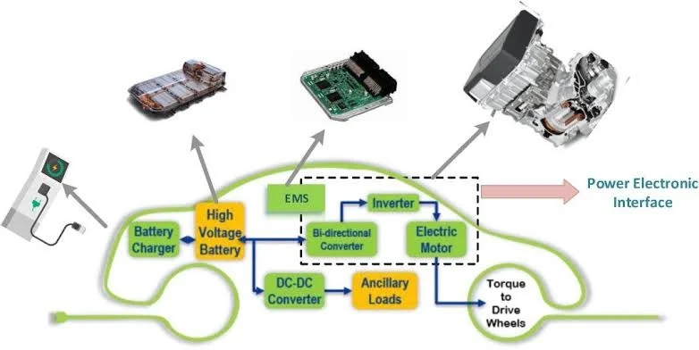
The power management system in modern electric vehicles (EVs) is a sophisticated electronic ecosystem whose performance directly determines the vehicle’s range, safety, and overall user experience. In this highly integrated system, Board-to-Board SMT connectors play a critical yet often underestimated role.
1.1 High Power Density Requirements: The Art of Miniaturized Power Transmission
Electric vehicle design philosophy is evolving toward “smaller, stronger, smarter.” As battery technology advances from conventional lithium-ion to solid-state batteries, and system voltage platforms increase from 400V to 800V and even 1000V levels, connectors face unprecedented power density challenges.
Industry data indicates that current mainstream EV energy conversion efficiency requirements exceed 95%, meaning connector contact resistance must be controlled at the milliohm level. In typical 800V platform EV architectures, each Board-to-Board connection point may need to carry continuous currents as high as 300A, while the packaging size often cannot exceed 70% of traditional solutions.
This miniaturization trend has driven innovative connector designs. Examples include high-density arrays of micro-contacts (with pitches as small as 0.5mm) combined with high-temperature conductive alloy materials (such as copper-chromium-zirconium alloys with conductivity reaching 85-90% IACS), achieving maximum current carrying capacity within limited installation space. Advanced plating technologies (like selective gold-palladium-nickel plating) not only ensure low resistance at contact points but also provide excellent wear resistance and oxidation resistance.
1.2 High-Temperature Environment Stability: Dual Challenges of Thermal Management Systems
Temperature management in EV battery systems is paramount in engineering design. While lithium-ion batteries operate optimally within 20-40°C, Joule heat generated during charging can cause localized temperatures to spike above 60°C.
Connectors in thermal cycling environments face two major challenges: first, matching coefficients of thermal expansion (CTE) among materials; second, the impact of long-term thermal aging on contact reliability. In typical SMT soldering processes, PCB materials (FR-4) have CTE around 14-18 ppm/°C, while common connector plastic housings (PBT or LCP) range from 20-30 ppm/°C. This mismatch in thermally harsh automotive environments can cause stress accumulation, potentially leading to solder joint cracking or connector warpage.
To address this, leading connector manufacturers have developed innovative “floating contact” designs and thermal compensation structures. Some premium series utilize split-contact designs that allow some Z-axis deformation margin, thereby absorbing thermal expansion stresses. Meanwhile, high-temperature-stable Liquid Crystal Polymer (LCP) materials are gradually replacing traditional PBT in critical applications, with CTEs controllable to 6-8 ppm/°C—almost perfectly matching PCB materials.
1.3 Vibration and Shock Endurance: Mechanical Stress Tests on the Road
Compared to conventional internal combustion vehicles, electric vehicles have simpler structures but significantly different vibration characteristics in powertrain systems. Permanent Magnet Synchronous Motor (PMSM) torque ripple and switching frequencies can generate high-frequency vibration components up to 2kHz, posing special requirements for electrical connections.
According to automotive industry standards (e.g., ISO 16750-3), onboard electronic components must withstand:
– Triaxial random vibration testing: 10-2000Hz range, acceleration up to 20g
– Mechanical shock: Half-sine wave, shock acceleration up to 500g
– Fatigue vibration resistance: Continuous testing for over 1000 hours
For Board-to-Board SMT connectors, this means contact interfaces must possess exceptional resistance to fretting wear. When vibration frequency nears natural frequencies of contact springs, resonance effects may occur, causing cyclic variations in contact pressure that ultimately lead to unstable increases in contact resistance.
—
Part 2: Advantages of SMT Technology in Automotive Electronics
Surface Mount Technology (SMT), since its emergence in the 1980s, has fundamentally transformed electronic manufacturing. In automotive electronics, this technology is not merely a manufacturing process revolution but a core infrastructure enabling vehicle electrification and intelligence.
2.1 Automated Production Efficiency: Imperative for Mass Manufacturing
The exponential growth of the EV market imposes stringent demands on manufacturing capabilities. Tesla’s Shanghai Gigafactory annual capacity exceeds one million vehicles, while the Volkswagen MEB platform’s global manufacturing system expands rapidly. In this context, production efficiency relates not only to costs but to delivery capability itself.
SMT technology’s advantages in automated production manifest in three dimensions:
First is equipment compatibility. Modern SMT production lines employ modular designs, seamlessly connecting printing machines, placement machines, and reflow ovens. This fully automated workflow reduces processing time per PCB to mere minutes, delivering at least 300% efficiency improvements over traditional Through-Hole Technology (THT) insertion-wave soldering processes. For automotive electronics manufacturers, this means a single production line can complete thousands of on-board control units (ECUs) daily.
Second is quality stability. SMT’s Automatic Optical Inspection (AOI) and X-ray inspection systems enable real-time monitoring of solder paste print quality, component placement accuracy, and soldering integrity. For example, modern laser alignment systems achieve placement accuracy of ±25μm for 0201-sized (0.2×0.1mm) components—a precision level critical for multi-pin connector alignment.
Finally is flexible manufacturing capability. As EV platform strategies proliferate, a single vehicle model may offer numerous configuration options. SMT production lines, through QR code identification and rapid program switching, can flexibly produce different PCB specifications on the same line, meeting automotive customization needs.
2.2 Space-Saving Design: New Paradigm for Compact ECU Packaging
“Space is performance” in EV design. Every cubic centimeter saved potentially increases battery capacity or improves thermal management.
Board-to-Board SMT connectors exhibit distinct advantages:
– Traditional THT solutions require heights of 8-10mm, requiring space for insertion/extraction on both PCB sides
– Modern SMT solutions compress heights to 3.5-4.5mm, may implement bottom-side mounting, and free up top space for heat sinks
But optimization extends beyond vertical dimensions. SMT connectors’ compact pin arrangements can shrink pitches to 0.4mm, reducing connector footprint by over 60% compared to traditional 2.54mm or 1.27mm pitches. Crucially, SMT allows connectors to mount directly to PCB surfaces without requiring through-hole drill space, freeing additional area for high-density routing.
2.3 Signal Integrity Optimization: Foundation for High-Speed In-Vehicle Networks
Rapid advancement of autonomous driving technology propels in-v ehicle networks from traditional CAN buses toward Ethernet backbones. Latest automotive Ethernet standards (e.g., 10BASE-T1S and 100BASE-T1) demand new levels of signal integrity.
SMT technology offers four primary advantages:
First is optimized signal paths. THT connectors require vertical conduction paths through via holes, introducing additional inductance and crosstalk. SMT’s direct surface contact design reduces signal path lengths by 30-40%, critical for minimizing signal delay and reflection losses.
Second is electrical parameter stability. Temperature variations and mechanical vibrations in automotive environments can alter contact interface characteristics. The robust mechanical bond formed by SMT soldering, combined with advanced contact geometries, can limit contact resistance variations to <10% over -40°C to 125°C. Third involves electromagnetic compatibility (EMC). Modern SMT connectors incorporate embedded shielding and optimized layouts, reducing electromagnetic radiation by 15-25dB to meet stringent CISPR 25 Class 3 requirements. Premium models even integrate common-mode chokes, implementing EMC filtering within the connector itself. Finally, manufacturing consistency ensures quality assurance. Precise control of soldering parameters (temperature profiles, solder paste volume, formulations) ensures highly uniform electrical characteristics for each pin interface—vital for guaranteeing consistent performance in mass production. — ## Part 3: Deep Analysis of Application Scenarios Electric vehicle electronic systems exhibit highly modular characteristics, with each subsystem imposing unique demands on Board-to-Board SMT connectors. Understanding these differentiated requirements is essential for optimized design and selection. ### 3.1 Battery Management Systems (BMS): Safety Monitoring’s Neural Endpoints Modern EV battery packs are no longer simple energy containers but complex management systems integrating hundreds or thousands of individual cells. BMS systems require connectors to provide absolutely reliable signal transmission in high-voltage environments. Voltage sensing connectors face micro-miniaturization challenges. Each module may contain 12-16 cells, each requiring simultaneous voltage monitoring. Such multi-point sensing demands high pin-density configurations (typically 30-50 pins) while ensuring electrical isolation between adjacent pins. Current industry trends employ 0.5mm pitch connectors with formulated insulation materials achieving insulation resistance of 10¹²Ω at DC 1000V. Temperature monitoring connectors confront thermal shock issues. Thermistor (NTC) circuits carry tiny signal currents (typically <1mA), yet connectors must survive rapid transitions from ambient temperatures to battery thermal runaway conditions (above 150°C). Advanced designs embed thermal sensing elements within connectors, outputting direct digital temperature signals via dedicated pins, reducing external wiring and potential failure points. ### 3.2 Motor Drive Inverters: Precise Balance of Power and Control Inverters converting battery DC to three-phase AC operate in a “three-high” environment: high voltage (400-800VDC), high current (hundreds of amperes continuous), and high switching frequency (IGBT/SiC switching up to 20kHz). Power device connection challenges concentrate on thermal management. Heat generated by IGBT or Silicon Carbide (SiC) modules requires rapid conduction to heat sinks through PCBs. Thus connectors must not only transmit power but also optimize thermal paths. Leading designs employ copper alloy bases forming “thermal bridges” on PCBs, quickly dissipating module-bottom heat. Control signal connectors face electromagnetic interference (EMI) challenges. PWM control signals with rise times of tens of nanoseconds generate strong electromagnetic radiation within closed loops. SMT connectors with differential signaling and shielding structures can suppress common-mode noise by >60dB, ensuring control signals remain isolated from power-stage interference.
3.3 In-Vehicle Infotainment Systems: Connectivity Pioneers of the Multimedia Era
Modern automotive cabins have evolved from driving spaces into mobile intelligent living environments, imposing unprecedented data transmission demands on connectors.
Video signal bandwidth requirements continue climbing. From initial LVDS (max 2.5Gbps) to current eDP (up to 32.4Gbps), supporting multi-display and 4K resolution now represents premium segment standards. Board-to-Board connectors must ensure signal integrity over long-distance transmissions (typically 300-500mm), with solutions including shielded FPC connectors and advanced models with built-in equalizers.
Audio system connections must balance audio quality and EMC performance. Adoption of Automotive Audio Bus (A2B) technology requires connectors supporting high-bandwidth, low-latency audio streams while isolating noise introduced by vehicle power systems.
3.4 ADAS Sensor Networks: Communication Arteries for Real-Time Decision Making
Advanced Driver Assistance Systems (ADAS) integrate multiple sensing sources—radar, cameras, LiDAR, and ultrasonic sensors—whose data require real-time processing in central computing units.
Sensor interfaces exhibit standardization trends. Traditional point-to-point custom interfaces gradually yield to standardized solutions, with FAKRA connector families already evolving toward miniaturization. For Board-to-Board connections, this means supporting higher-frequency RF transmissions, with specialized models already stabilizing millimeter-wave radar signals above 30GHz.
Data fusion connectors confront synchronization challenges. Multi-camera system timestamp alignment demands microsecond-level precision, requiring connectors to ensure not only data transmission but also clock signal jitter control. SMT connectors with low-latency designs and precise impedance control (±5%) have become preferred solutions.
Conclusion
Board-to-board SMT connectors play a critical role in modern electronic systems, from electric vehicles to industrial automation. Selecting the right connector requires careful evaluation of pitch, current rating, signal integrity, and environmental requirements. Longyueda offers a full range of BTB SMT connectors designed to meet these diverse application needs.
Frequently Asked Questions
What is a board-to-board SMT connector?
A board-to-board SMT connector uses Surface Mount Technology to directly solder connector terminals onto PCB pads. It provides a reliable mechanical and electrical connection between two PCBs without cables, supporting high-density designs in compact electronic assemblies.
What pitch sizes are available for BTB SMT connectors?
Common pitch sizes include 0.4mm for ultra-compact devices, 0.8mm for general-purpose electronics, 1.0mm and 1.27mm for industrial applications, and 2.54mm for breadboard-compatible designs. Longyueda offers connectors across all these pitch ranges.
What is the typical current rating for an SMT BTB connector?
Current ratings vary by pitch and pin count: 0.4-0.8mm pitch connectors typically handle 0.5-3A per pin, while larger pitch (1.27-2.54mm) connectors can support 3-5A per pin. Always verify derating guidelines for your specific application.
How to ensure reliable SMT soldering for BTB connectors?
Key factors include proper stencil design for solder paste volume, accurate pick-and-place alignment, optimized reflow profile for the connector material (LCP or PA9T), and AOI for solder joint quality verification.
📡 Download BTB SMT Connector Datasheet & Request Samples →
Explore our board-to-board connector selection guide and 0.8mm BTB connector technical guide for detailed selection information.
