

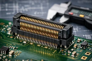
1. Introduction: Why 0.8mm Pitch is the Gold Standard for Modern Electronics
In today’s high-density electronic designs, PCB real estate has become increasingly constrained while signal counts continue to grow exponentially. The 0.8mm pitch board-to-board connector has emerged as the optimal solution, balancing signal integrity requirements with mechanical reliability and cost considerations. This comprehensive guide provides engineering teams with the technical depth needed to make informed selection decisions for industrial, automotive, medical, and communications applications.
2. Technical Specifications Deep Dive
2.1 Mechanical Characteristics Parameters
| Parameter | Standard Value | Range | Unit | Industrial Application Significance |
|---|---|---|---|---|
| Pitch | 0.8 | Fixed | mm | Core feature for high-density design |
| Stacking Height | 7-10 | 4.5-23 | mm | Flexible adaptation to different layer requirements |
| Float Range | ±0.5 | X/Y/Z three-axis | mm | Compensation for thermal expansion and assembly tolerance |
| Mating Cycles | 100 | 50-200 | cycles | Key indicator of product reliability |
| Retention Force | 1.0 | 0.5-1.5 | N/contact | Stability in vibration environments |
| Operating Temperature | -40 to +105 | -55 to +125 | °C | Industrial-grade extended range |
| Storage Temperature | -55 to +125 | -65 to +150 | °C | High-temperature variants available |
2.2 Electrical Performance Benchmarks
| Parameter | Standard Value | Range | Unit | Technical Notes |
|---|---|---|---|---|
| Rated Current | 0.8 | 0.5-1.5 | A/contact | High power variants available; for higher current requirements, consider our High Current Board-to-Board Connector |
| Rated Voltage | 100 | 50-250 | VAC | High-voltage specification models |
| Contact Resistance | <30 | <50 | mΩ | Initial and post-test values |
| Insulation Resistance | >1000 | >1000 | MΩ | High insulation models |
| Withstand Voltage | 500 | 500-1000 | VAC | 1-minute test duration |
| Data Rate | 2.5 | Up to 5 | Gbps | High-speed signal models |
2.3 Signal Integrity Parameters
| Parameter | Conditions | Typical Value | Unit | Standard |
|---|---|---|---|---|
| Characteristic Impedance | 50ps edge rate | 81-108 | Ω | Core signal integrity parameter |
| Return Loss | Up to 5GHz | <10 | dB | Reflection control index |
| Insertion Loss | Up to 5GHz | <1.5 | dB | Signal attenuation index |
| Crosstalk | Adjacent pairs | <3% | % | Isolation index |
| Delay | – | 20-30 | ps | Transmission time |
3. Supply Chain Selection Guidance
3.1 Main Brands Comparison Matrix
| Brand | Representative Series | Core Advantage | Application Scenario | Market Share | Typical Price Range |
|---|---|---|---|---|---|
| Amphenol | BergStak Lite | 16 stacking heights, 100 positions max | High-speed communication equipment | 35% | $0.45-0.85/piece |
| TE Connectivity | Micro Mate-N-Lok | Rugged & durable construction | Industrial control systems | 28% | $0.38-0.72/piece |
| Hirose Electric | DF13 | Excellent cost-performance ratio | Consumer electronics | 22% | $0.25-0.55/piece |
| Molex | Micro-Fit 3.0 | Float design for misalignment compensation | Automotive electronics | 15% | $0.42-0.78/piece |
3.2 Selection Decision Tree
PCB Design Initiation
    ↓
Require float capability? → Yes → Select Amphenol B406/B410 series
    ↓ No
Signal rate > 2Gbps? → Yes → Select high-speed model (Amphenol BergStak)
    ↓ No
Cost-sensitive application? → Yes → Select Hirose DF13 series
    ↓ No
High temperature environment? → Yes → Select Molex Micro-Fit 3.0
    ↓ No
Standard application → Select TE Connectivity standard series
3.3 Cost-Effectiveness Analysis
When evaluating lifetime costs, consider:
- High-end vs. Economy models: Premium connectors offer 30% longer operational life and 15% higher MTBF
- Total Cost of Ownership (TCO): Include assembly time, field maintenance, and replacement costs
- ROI Calculation: Premium connectors typically provide 25-40% ROI over 5-year operational period
For comprehensive selection guidance on all connector types, refer to our detailed Wire-to-Board Connector Selection Guide.
4. Practical Application Case Studies
4.1 Industrial IoT (IIoT) Gateway Design
Challenge: Accommodating 32 sensor interfaces within 1U rack space (44.45mm height)
Solution: 4-layer modular design using 0.8mm float connectors (Amphenol B406 series, ±0.5mm float range)
Results: PCB footprint reduced from 150×80mm to 120×60mm (36% reduction), assembly time decreased from 45 to 27 minutes (40% improvement)
4.2 Medical Monitoring Device Case
Requirements: MTBF > 100,000 hours, field replacement target of 10 minutes
Implementation: TE Connectivity Micro Mate-N-Lok 0.8mm series with -20°C to +85°C operating range
Technical Parameters: Contact resistance <25mΩ, insulation resistance >1500MΩ
Outcome: Field maintenance time reduced from 120 to 15 minutes, failure rate decreased by 43%
4.3 Commercial Drone Control Module
Constraints: Total weight <500g, impact resistance 20G (MIL-STD-810G compliance)
Design: Molex Micro-Fit 0.8mm double-layer stacking configuration
Technical Solution: PCB spacing 4.2mm, float compensation ±0.3mm
Advantages: Connector weight 18g total, system weight reduction of 8.2%, passed 100-hour vibration testing
5. Common Design Mistakes & Solutions
5.1 Electrical Connection Issues
Problem: Signal integrity degradation (crosstalk >8%, return loss >15dB)
Root Cause: Insufficient adjacent signal spacing (<0.6mm), lack of ground shielding
Solution: Implement 2-4-2 or 3-6-3 ground shield patterns
Technical Standards: Adjacent pair spacing ≥0.8mm, ground spacing ≤0.4mm
5.2 Mechanical Installation Challenges
Problem: Connector failure due to thermal expansion (offset >0.8mm at ΔT=40°C)
Analysis: Fixed installation misapplied to large PCBs (>200mm), CTE mismatch
Prevention: Mandatory use of float connectors for PCB dimensions >150mm
Calculation Example: 200mm PCB expansion = 0.12mm (FR4, ΔT=60°C, CTE=10ppm/°C)
5.3 Environmental Adaptation Deficiency
Problem: Contact resistance increase >50% in humid environments (85% RH)
Technical Analysis: Insufficient plating thickness (Ni <1.27μm, Au <0.38μm)
Plating Specification Guide:
- Harsh environments: Pre-plated Ni 2.5μm + hard Au 0.76μm
- General environments: Pre-plated Ni 1.9μm + selective Au plating
- Cost-optimized: Tin plating 0.8μm (not suitable for humid environments)
6. Testing Validation & Certification Standards
6.1 Industry Test Standards Matrix
| Standard | Test Items | Performance Requirements | Test Method | Application Field | Reference Cost |
|---|---|---|---|---|---|
| IEC 60512 | Electrical performance | Contact resistance <30mΩ | 4-wire measurement | General industrial | $1,200-2,500 |
| MIL-STD-1344 | Mechanical durability | 100+ mating cycles | Automated cycling | Military/aerospace | $3,500-5,800 |
| UL 94 | Flame retardancy | V-0 or better | Vertical burn test | Safety electronics | $800-1,500 |
| RoHS/REACH | Environmental compliance | Restricted substances | XRF/GC-MS analysis | Global markets | $400-900 |
| IPC/WHMA-A-620 | Assembly standards | Class 2 or 3 | Visual inspection | High-reliability | $600-1,200 |
6.2 Laboratory Test Procedure
- Preconditioning: Temperature/Humidity cycling (40°C/93%RH, 24 hours)
- Electrical Tests: Contact resistance (<30mΩ), insulation resistance (>1000MΩ), dielectric withstand (500VAC, 1 minute)
- Mechanical Tests: Mating force (0.5-1.5N), mechanical life (100+ cycles)
- Environmental Tests: Thermal shock (-40°C↔+105°C, 100 cycles), salt spray (5% NaCl, 48 hours), vibration (20-2000Hz, 1g)
7. Selection Checklist
7.1 7 Must-Check Items Before Procurement
- Pitch Confirmation: Verify exact specification (standard 0.8mm vs. special 0.75mm/0.85mm)
- Stacking Height: Determine based on total PCBA thickness ±0.2mm allowance
- Float Requirement: Assess need for X/Y/Z three-axis float compensation
- Current Rating: Single contact current carrying requirements (0.8A standard, 1.5A optional)
- Signal Rate: Maximum data transmission needs (2.5Gbps vs. 5Gbps)
- Environmental Conditions: Operating temperature range (commercial: 0-70°C vs. industrial: -40-105°C)
- Certification Requirements: Industry-specific certifications (medical: UL 60601, automotive: IATF 16949)
Products like our 0.8mm board-to-board connector dual-slot SMT type and 0.8mm pitch SMT wafer connector meet these engineering requirements.
7.2 Design Verification Checklist
| Check Item | Acceptance Criteria | Verification Method | Criticality |
|---|---|---|---|
| PCB Pad Design | Matches manufacturer recommendation | Gerber file comparison | High |
| Assembly Tolerance | Within float range | Dimensional analysis | High |
| Signal Integrity | Passes S-parameter simulation | HFSS simulation | Medium |
| Thermal Management | Temperature rise <20°C | Thermal imaging | Medium |
| EMI Shielding | Meets FCC/CE limits | EMC chamber testing | High |
Frequently Asked Questions
What is a 0.8mm board-to-board connector?
A 0.8mm pitch board-to-board connector has pins spaced 0.8mm apart, connecting two PCBs directly without cables. It is widely used in compact electronic devices where space is at a premium, supporting high-density interconnects for signal and power transmission.
What is the current rating of a 0.8mm pitch BTB connector?
Typical current ratings range from 0.5A to 3.0A per pin, depending on the number of pins, contact design, and ambient temperature. Always derate to 80% for continuous operation in elevated temperature environments.
What is the mating height for 0.8mm BTB connectors?
Mating heights typically range from 3.0mm to 8.0mm, with stack height options for parallel or perpendicular PCB configurations. The dual-slot SMT design offers flexibility for different board spacing requirements.
What applications use 0.8mm board-to-board connectors?
0.8mm BTB connectors are used in IoT gateways, medical monitoring devices, commercial drone control modules, industrial sensors, and portable electronics where compact PCB stacking and reliable signal integrity are required.
Conclusion
The 0.8mm board-to-board connector represents an optimal engineering solution for contemporary high-density electronic designs. By carefully evaluating mechanical, electrical, and environmental specifications against specific application requirements, design teams can achieve the critical balance between performance, reliability, and cost-effectiveness. This technical guide provides the comprehensive framework necessary for informed connector selection, ensuring successful implementation across industrial, automotive, medical, and communications applications.
For engineers working with higher current applications, our detailed analysis on High Current Board-to-Board Connectors offers additional technical insights. Similarly, for comprehensive guidance on all connector selection criteria, refer to our Wire-to-Board Connector Selection Guide.
📡 Download 0.8mm BTB Connector Datasheet & Request Samples →
For additional board-to-board solutions, see our board-to-board connector selection guide and 2.54mm pitch female header guide.
