Vertical USB C Female SMT Connector – Engineering Guide for 24-Pin Top-Entry Designs
1. Introduction: The Role of Vertical USB-C in Modern PCB Design
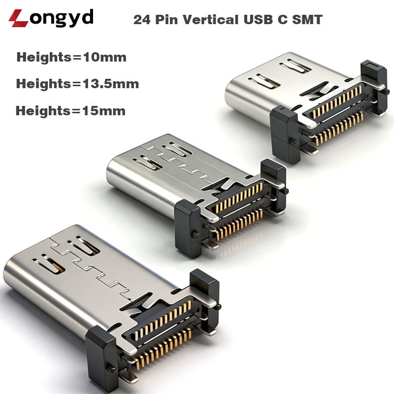
As electronic enclosures become thinner and component density increases, the vertical USB C female SMT connector has emerged as a critical solution for design engineers who need a reliable, space-efficient top-entry USB-C interface. Unlike traditional right-angle USB-C receptacles that route the cable parallel to the PCB, the vertical (perpendicular) orientation allows the cable to plug in from above — an essential feature for stackable boards, panel-mounted ports, and compact industrial housings.
The 24-pin full-featured variant supports USB 3.2 Gen2 (10 Gbps), USB Power Delivery up to 5 A, and DisplayPort Alt Mode, making it a single-connector solution for power, data, and video. This guide covers the technical specifications, mechanical considerations, and application best practices for engineers evaluating the vertical USB-C receptacle family.
2. Key Technical Specifications
The following table summarizes the core electrical and mechanical parameters for the vertical USB C 24-pin female SMT receptacle series:
| Parameter | Specification |
|---|---|
| Interface Type | USB Type-C Female, 24-Pin Full Featured |
| Available Heights | 10.0 mm / 13.5 mm / 15.0 mm |
| Current Rating | 5.0 A Max (VBUS, GND) |
| Contact Resistance (Initial) | ≤ 30 mΩ |
| Contact Resistance (After Test) | ≤ 40 mΩ |
| Insulation Resistance | ≥ 100 MΩ |
| Dielectric Withstanding Voltage | 500 V AC / 1 min |
| Durability | 10,000 Cycles |
| Operating Temperature Range | -30 °C to +85 °C |
| Shell Material | Stainless Steel (SUS304) |
| Contact Material | Copper Alloy, Gold Plating |
| Mounting Method | Hybrid: SMT Signal Pins + DIP Shell Legs |
| Packing Options | Tape & Reel / Tray |
The hybrid mounting design is a key differentiator. Signal pins are configured for precision SMT reflow soldering, while the four robust shell legs insert into through-holes (DIP) on the PCB. This combination delivers strong mechanical retention — an advantage over pure-SMT USB-C connectors that are more vulnerable to lift-off during cable insertion and extraction.
3. Understanding the Three Height Options: Mechanical Stacking Guide
The vertical USB C female SMT connector family is offered in three standard profile heights to accommodate different enclosure depths and PCB stacking requirements.
| Height | Best For | Considerations |
|---|---|---|
| 10.0 mm | Ultra-thin portable devices, wearables, compact IoT gateways | Lowest profile; ensure cable plug clearance above enclosure |
| 13.5 mm | Industrial controllers, docking stations, test equipment | Standard mid-range; compatible with most USB-C cable boots |
| 15.0 mm | Thick-walled enclosures, high-heat assemblies with thermal gap pads | Tallest option; provides clearance for conformal coating or thermal management layers |
Selection guideline: Measure the total available height from the top of the PCB to the interior surface of the enclosure lid, then subtract the cable plug height (typically 6.0-6.5 mm for standard USB-C plugs). The remaining clearance should be at least 1.0 mm. The 13.5 mm height is the most versatile choice for general industrial applications.
4. Hybrid Mounting: Why SMT + DIP Shell Anchoring Matters
A common failure mode in USB-C connectors is shell lift-off caused by repeated cable insertion and removal. Purely surface-mount receptacles rely entirely on solder joint strength at the shell anchor pads, which can crack over time, especially in high-cycle or vibration-prone environments.
The vertical USB C female SMT connector series addresses this through a hybrid mounting architecture:
- Signal pins (SMT): 24 pins are designed for reflow soldering, enabling high-speed automated placement and consistent solder joint geometry. Reflow profiling should target a peak temperature of 245-260 °C with a soak zone between 150-200 °C for 60-90 seconds.
- Shell legs (DIP): Four stainless steel legs extend through the PCB and are wave-soldered or hand-soldered. These through-hole anchors provide mechanical pull-out strength that pure SMT cannot match.
For engineers designing with SMT female header connectors, the same hybrid principle applies: using through-hole anchoring for stress-bearing elements while reserving SMT for high-density signal routing yields the best reliability outcome.
| Mounting Method | Pull-Out Strength | Assembly Complexity | Rework Difficulty |
|---|---|---|---|
| Pure SMT | Low (20-40 N typical) | Low (single reflow) | Moderate |
| Pure DIP | High (80-120 N) | High (wave solder + manual) | High |
| Hybrid (SMT + DIP) | High (80-100 N) | Moderate (reflow + selective wave) | Moderate |
5. USB-C 24-Pin Full Features: What Engineers Actually Get
The 24-pin full-featured pinout is what distinguishes a true USB-C connector from a simplified charging-only variant. Here is what each functional group delivers in this vertical USB C connector 24 pin design:
- USB 3.2 Gen2 (10 Gbps): Two high-speed differential pairs (SSTXp/n, SSRXp/n) on both sides of the receptacle enable full SuperSpeed+ data rates. Signal integrity is maintained through controlled impedance (90 Ω ±15% differential) and matched trace lengths on the PCB.
- USB Power Delivery 3.0 (5 A): Four VBUS pins and four GND pins in parallel handle up to 5 A continuous current. The CC1/CC2 pins manage PD negotiation, role detection, and current capability advertisement.
- DisplayPort Alt Mode: The SBU1/SBU2 sideband channels carry DP auxiliary signals, while the high-speed pairs can be reconfigured for DisplayPort main link lanes — enabling 4K video output through a single connector.
- Configuration Channel (CC): CC1 and CC2 are used for cable orientation detection, power role negotiation, and alternate mode entry. Proper ESD protection (≤ 0.5 pF capacitance) is recommended on these lines.
6. Reliability & Environmental Performance
The USB Type C vertical female connector is rated for 10,000 mating cycles, tested under standard USB-IF procedures. This rating assumes the receptacle is mounted on a rigid PCB with adequate support beneath the connector body. Key reliability characteristics include:
- Contact resistance stability: Initial ≤ 30 mΩ; after 10,000 cycles ≤ 40 mΩ. The gold-plated copper alloy contacts resist oxidation and maintain low resistance over the product lifetime.
- Temperature range (-30 °C to +85 °C): Suitable for automotive cabin, outdoor telecommunications, and unconditioned industrial environments. The LCP (Liquid Crystal Polymer) insulator maintains dimensional stability across the full temperature range, with a heat deflection temperature exceeding 260 °C.
- Corrosion resistance: The SUS304 stainless steel shell provides excellent resistance to humidity and mild chemical exposure. For environments requiring submersion protection, see the waterproof USB C 24 pin connector series, which integrates a silicone sealing gasket for IPX7-rated applications.
7. Complementary Products & Application Notes
When designing a complete USB-C interface solution, the vertical receptacle is often paired with complementary components:
- EMI shielding: For high-speed USB 3.2 Gen2 operation, a metal shell with grounding clips or a conductive gasket around the receptacle cutout helps contain radiated emissions.
- ESD protection: Low-capacitance TVS diodes (≤ 0.5 pF) on CC, SBU, and D+/D- lines are recommended to meet IEC 61000-4-2 Level 4 (8 kV contact / 15 kV air) requirements.
- PCB layout notes: Route high-speed differential pairs with 90 Ω ±10% differential impedance. Keep VBUS traces at a minimum of 2.0 mm width for 5 A applications. Provide thermal relief on DIP shell leg pads for improved wave soldering.
The vertical orientation is ideal for docking stations, industrial HMI panels, and test fixtures where the cable enters from above. For applications requiring a cable exit parallel to the board, a right-angle USB-C receptacle should be considered instead.
8. Conclusion
The vertical USB C female SMT connector offers design engineers a mechanically robust, full-featured USB-C solution for top-entry applications. With three height options (10.0, 13.5, and 15.0 mm), hybrid SMT+DIP mounting, and full 24-pin support for USB 3.2 Gen2, PD, and DP Alt Mode, it is a versatile choice for industrial, automotive, and consumer applications where space efficiency and reliability are critical.
Technical drawings, 3D models, and sample requests are available. Contact our engineering team to discuss your specific height, plating, and packaging requirements.
