

1.25mm Pitch Shielded Wire Crimping
Frequently Asked Questions
What is 1.25mm pitch shielded wire crimping?
Crimping fine-pitch connectors with 1.25mm spacing using shielded wire. Tight pitch demands precise terminal alignment, controlled crimp height, and proper shield termination.
Why is automation not always the answer?
Fine-pitch crimping needs operator feel. Automated machines handle volume but need careful setup. Semi-automatic offers better flexibility for precision low-volume runs.
What quality checks are critical?
Crimp height, pull force testing, cross-section analysis, and terminal alignment inspection. Pull test should read within 15% of specified range.
In an era where “fully automatic” is the industry buzzword, there are still specific frontier challenges where the human touch and expert calibration reign supreme. One such challenge is the crimping of 1.25mm pitch terminals onto multi-core shielded wires.
Because of the complex structure of shielded cables—combining delicate inner cores, foil or braided shielding, and varying insulation thickness—fully automatic machines often struggle with consistency. Today, we’re diving into why manual expertise and rigorous Pull Force Testing are the true anchors of quality in this high-precision process.
Why Automation Isn’t Always the Answer
While full automation excels at standard single-wire processing, the 1.25mm shielded wire presents unique hurdles:
- Complex Internal Structure: Shielded wires require careful stripping to ensure the ground wire and signal cores are perfectly separated without damaging the hair-thin copper strands.
- Miniaturization: A 1.25mm pitch leaves zero room for error. A deviation of even 0.05mm in the crimp applicator can lead to a “cracked” terminal or a weakened connection.
- Material Sensitivity: The fine gauge wires (often AWG 28-32) used in these assemblies are prone to bending or misfeed in high-speed automated tracks.
To solve this, we utilize semi-automatic crimping combined with expert manual alignment, ensuring every wire is seated perfectly before the press cycles.
The Engineer’s “Feel”: Machine Calibration
As shown in our workshop photos, the setup process is a delicate balance of mechanics and experience. A master technician doesn’t just “set” the machine; they tune it. Key focus areas include:
- Crimp Height (CH) Optimization: Finding the “sweet spot” where the terminal wings grip the wire tight enough to ensure electrical conductivity, but not so tight that they sever the delicate copper strands.
- Visual Alignment: Ensuring the terminal is perfectly centered under the ram to avoid “bell-mouth” defects or lopsided crimps.
The Gold Standard: Pull Force Testing
How do we prove that a “manual” process meets “industrial” standards? Through data.
As seen in the second image, we use a High-Precision Tension Tester to perform destructive testing on sample pieces after every machine setup.
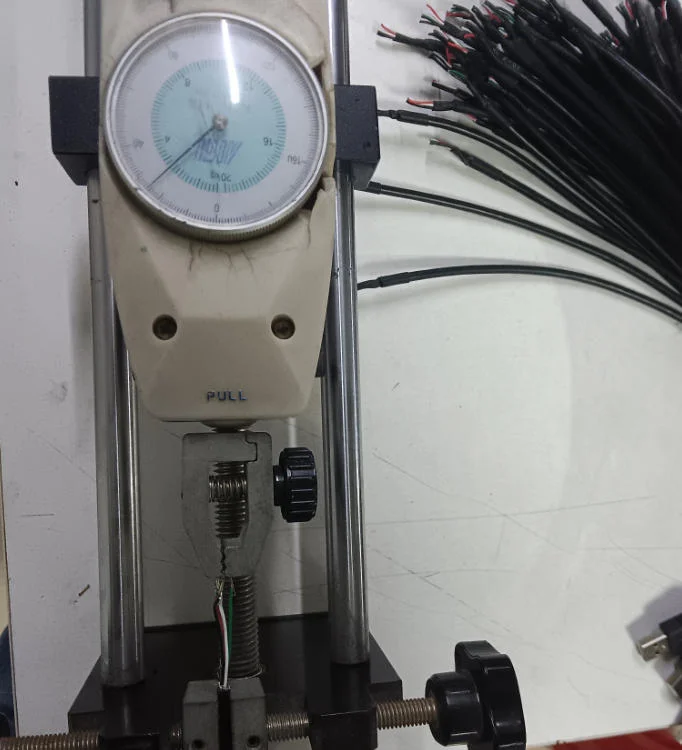
- Fixed Clamping: The wire is secured in the lower grip, while the terminal is hooked into the upper pulling head.
- Linear Tension: The machine applies a steady, increasing force until the wire pulls out or breaks.
- Data Verification: We compare the peak force on the dial against international standards (such as IPC-A-620). For a 1.25mm terminal on thin wire, the pull-off force must meet strict minimums to ensure the harness survives the vibrations and stresses of real-world use.
Engineer’s Note: “A perfect crimp is invisible to the eye, but the pull tester never lies. If the dial doesn’t hit the target, we go back to the calibration bench.”
In high-end electronics manufacturing, technology provides the tools, but experience provides the reliability. By combining the steady hand of an experienced operator with the objective proof of pull-force testing, we ensure that every 1.25mm shielded connection is built to last.
Do you face challenges with miniaturized wire harnesses? Let’s discuss the best practices for quality control in the comments below.
www.lyd123.com Email: nick.xu@lyd123.com
📡 Download Wire Crimping Process Guide & Request Samples →
Explore our wire-to-board selection guide and board-to-board connector guide for more engineering resources.
