

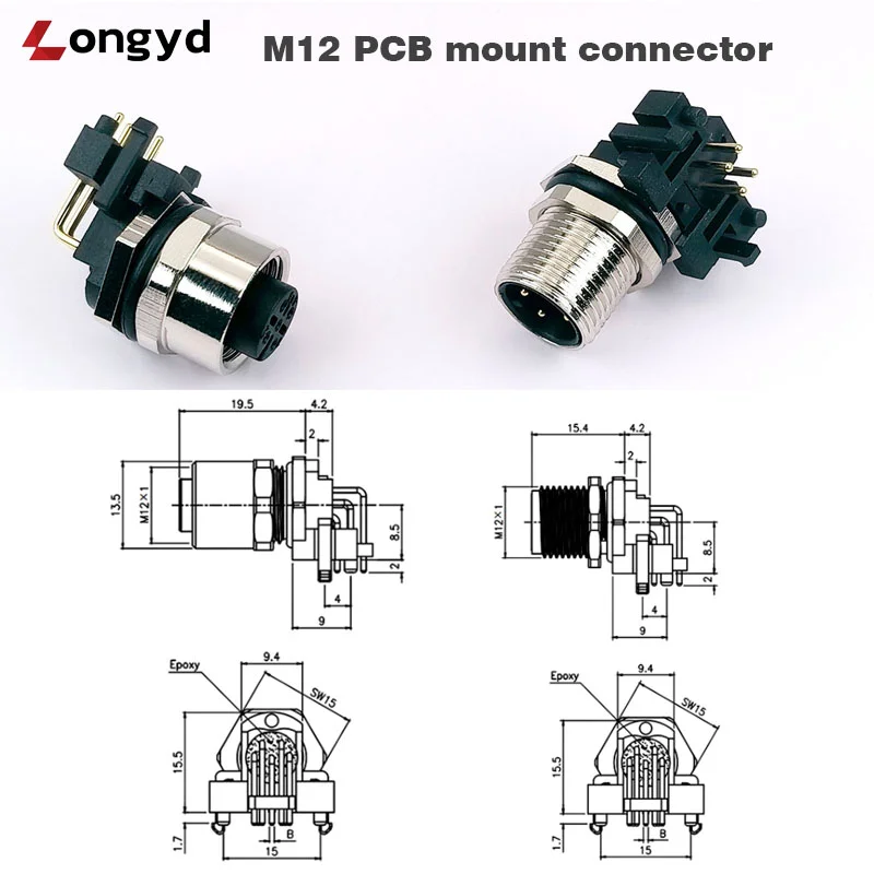
Introduction: The Role of M12 Connectors in Industrial Automation
M12 connectors have become the de facto standard for industrial sensor connectivity, fieldbus communication, and power distribution in factory automation environments. Their compact circular form factor, robust threaded coupling, and wide range of coding options (A, B, C, D) make them suitable for diverse applications—from proximity sensors and actuators to PROFINET and EtherCAT networks.
LYD’s IP67 M12 right-angle PCB mount connector combines the proven reliability of the M12 interface with a space-saving right-angle form factor and integrated IP67 sealing, making it ideal for PCB-based applications where panel space is limited and environmental protection is critical.
Key Specifications: IP67 M12 Right-Angle PCB Mount Connector
- Connector Type: M12 circular threaded (per IEC 61076-2-101)
- Mounting Style: Right-angle PCB mount (through-hole / SMT compatible)
- Coding Options: A-coding (sensors/actuators), B-coding (fieldbus), C-coding (dual-power), D-coding (Ethernet)
- Ingress Protection: IP67 (mated with panel seal)
- Contact Material: Gold-plated brass or phosphor bronze
- Housing Material: Nickel-plated brass or stainless steel
- Insulator Material: PA66 / LCP (UL94 V-0 rated)
- Operating Temperature: -25°C to +85°C
- Mating Cycles: ≥100 cycles
- Applications: Industrial sensors, automation controllers, I/O modules, fieldbus devices
Why Choose Right-Angle PCB Mount M12 Connectors?
1. Space Optimization
Traditional straight (axial) M12 PCB connectors extend perpendicularly from the board, requiring significant clearance in the direction of the cable exit. The right-angle configuration allows the connector to sit parallel to the PCB, reducing the overall height profile and enabling denser board layouts. This is especially valuable in compact I/O modules, distributed control boxes, and space-constrained sensor interfaces.
2. Improved Cable Management
Right-angle connectors naturally route cables parallel to the PCB plane, reducing cable strain at the connector interface and simplifying enclosure design. Cable exit direction can be controlled by selecting between 90-degree orientations, allowing cleaner routing within the system enclosure.
3. Enhanced Mechanical Stability
The PCB mount design provides secure mechanical retention through soldered through-hole pins. Combined with the right-angle form factor that distributes insertion/withdrawal forces along the board plane rather than perpendicular to it, these connectors offer superior vibration resistance compared to cable-mounted M12 connectors.
Understanding M12 Coding Options
One of the key advantages of the M12 connector system is the mechanical keying that prevents mismating between different signal types:
| Coding | Pin Count | Typical Application | Signal Type |
|---|---|---|---|
| A-coded | 3, 4, 5, 8 | Sensors, actuators, DC power | Digital I/O, analog, 24V power |
| B-coded | 4, 5 | Fieldbus (DeviceNet, Profibus) | RS-485, CAN bus |
| C-coded | 3, 4, 5 | Dual-power AC motors | Power + signal |
| D-coded | 4 | Industrial Ethernet (PROFINET, EtherNet/IP) | 100 Mbps Ethernet |
The LYD IP67 M12 right-angle PCB mount connector supports A/B/C/D coding configurations, providing flexibility across multiple industrial applications from a single PCB footprint design.
IP67 Protection for Industrial Environments
IP67-rated sealing ensures the M12 connector maintains reliable operation in the challenging conditions typical of industrial automation:
- Machining & manufacturing: Protection against coolant mist, metal shavings, and wash-down
- Food & beverage processing: Withstands high-pressure wash-down and chemical cleaning agents
- Outdoor installations: Rain, snow, dust, and UV exposure resistance
- Wastewater & water treatment: Humid, corrosive atmosphere protection
The integrated panel-mount seal provides IP67 protection at the panel interface when properly installed with the recommended mounting torque.
PCB Design Considerations for M12 Right-Angle Connectors
Footprint Layout
The M12 right-angle PCB mount connector requires careful footprint planning to ensure proper alignment with the panel cutout. Key considerations include:
- Hole diameter: Match the connector pin diameter with appropriate PCB hole size for optimal solder fillet formation
- Panel cutout: The mounting flange requires a precise circular cutout (typically 16–18mm diameter) with threaded mounting holes
- Keep-out zone: Reserve clearance around the connector body for the mating cable connector and finger access
Mechanical Mounting
For applications subject to vibration (e.g., robotics, conveyors, vehicle-mounted equipment), the PCB should be secured with additional mounting screws through the connector’s flange holes. The right-angle design’s low profile also benefits from edge-mount positioning near the PCB perimeter.
Electrical Considerations
Gold-plated contacts provide stable, low-resistance connections suitable for both power (up to 4A per contact for A-coded) and signal (up to 100 Mbps for D-coded Ethernet). PCB trace routing should maintain appropriate impedance control for high-speed signals when using D-coded configurations.
Comparative Analysis: M12 vs. M8 vs. RJ45 for Industrial Applications
| Feature | M12 Connector | M8 Connector | RJ45 Connector |
|---|---|---|---|
| Thread Size | M12 × 1.0 | M8 × 1.0 | N/A (latch) |
| Current Capacity | Up to 4A (signal) / 12A (power) | Up to 3A | 1.5A max |
| IP Rating | IP67 (standard) | IP67 (standard) | IP20 (standard) / IP67 (special) |
| Coding Variants | A, B, C, D, X, S, T | A, B, D | N/A |
| Ethernet Support | Up to 10 GbE (X-coded) | Up to 100 Mbps (D-coded) | Up to 10 GbE (Cat6a) |
| PCB Mount Options | Right-angle, straight, panel | Right-angle, straight | Vertical, right-angle |
Installation Guide
- Panel preparation: Cut or drill the panel to the specified diameter (refer to mechanical drawing for exact dimensions). Clean and deburr the cutout.
- PCB insertion: Insert the connector pins through the PCB holes. Ensure the connector sits flush against the board surface.
- Soldering: Wave solder or hand-solder the pins. Verify proper wetting and fillet formation on all contacts.
- Panel mounting: Secure the PCB/connector assembly to the panel using the threaded flange and appropriate gasket or O-ring.
- Torque specification: Tighten the mating cable connector to 0.6 N·m (recommended) — use a torque wrench for consistent sealing.
- Verification: Perform continuity test on all contacts and visual inspection of the panel seal.
Conclusion
The LYD IP67 M12 right-angle PCB mount connector offers industrial equipment designers a reliable, space-efficient interconnect solution for sensor, actuator, and communication interfaces. With multi-coding support, robust IP67 sealing, and a proven PCB mount format, this connector simplifies enclosure design while ensuring long-term reliability in demanding factory automation environments.
For detailed specifications, CAD models, and OEM pricing, contact LYD’s engineering team or visit the product page:
Related Resources
For high-current power connectivity in industrial systems, see our Energy Storage Quick-Lock Connector Guide covering 200A and 80A IP67 solutions.
For an in-depth engineering analysis of waterproof terminal post technology, read our IP67 Waterproof Terminal Post Deep-Dive.
