Introduction: The Manufacturing Criticality of Precision Battery Connectors
While technical specifications and application guidelines form the theoretical foundation of connector performance, it is in the manufacturing realm where 2.0mm pitch blade battery connectors truly achieve their reliability and consistency. As these components increasingly find applications in safety-critical systems like electric vehicle battery management and medical equipment, the manufacturing processes and quality control protocols become paramount determinants of field performance and longevity.
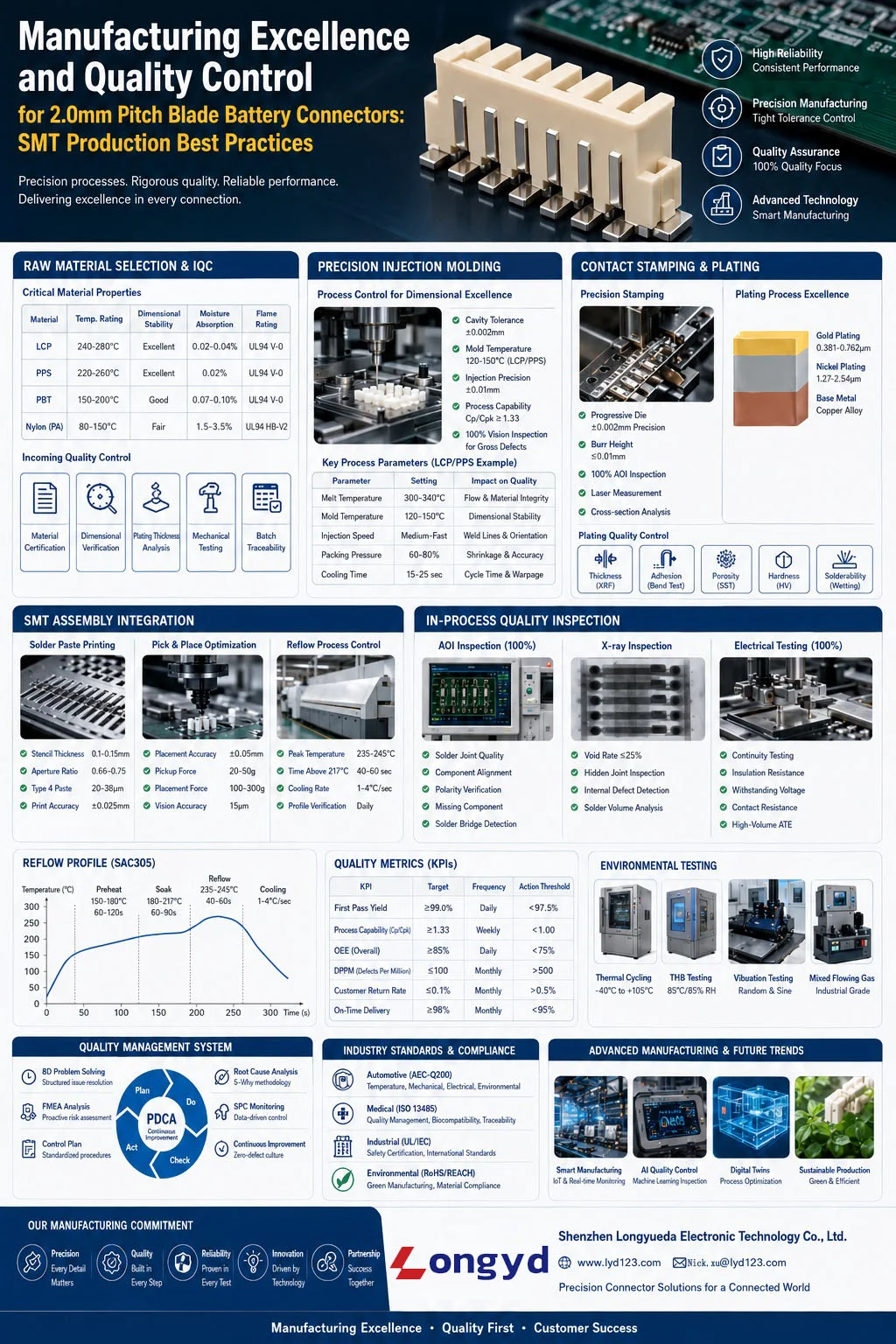
This comprehensive guide examines the manufacturing excellence methodologies, quality assurance frameworks, and production best practices essential for producing reliable 2.0mm pitch SMT blade connectors for demanding battery applications.
Raw Material Selection and Incoming Quality Control
Critical Material Properties and Specifications
Housing Materials
For 2.0mm pitch blade connectors, housing material selection is governed by competing requirements:
| Material Type | Temperature Rating | Dimensional Stability | Moisture Absorption | Flame Rating | Typical Applications |
|---|---|---|---|---|---|
| LCP (Liquid Crystal Polymer) | 240-280°C | Excellent | 0.02-0.04% | UL94 V-0 | Automotive, High-Temp |
| PPS (Polyphenylene Sulfide) | 220-260°C | Excellent | 0.02% | UL94 V-0 | Industrial, Medical |
| PBT (Polybutylene Terephthalate) | 150-200°C | Good | 0.07-0.10% | UL94 V-0 | Consumer Electronics |
| Nylon (PA) | 80-150°C | Fair | 1.5-3.5% | UL94 HB-V2 | Low-Cost Applications |
Contact Plating Specifications
The critical plating parameters for reliable electrical performance:
- Base Material: Phosphor bronze or copper alloy (C5191, C5210, etc.)
- Nickel Barrier Layer: 1.27-2.54μm (50-100μ”) minimum
- Gold Plating Thickness:
- Low-Level: 0.127-0.254μm (5-10μ”) for signal contacts
- Standard: 0.381-0.762μm (15-30μ”) for power contacts
- High-Reliability: 0.762-1.270μm (30-50μ”) for demanding applications
- Selective Plating: Critical for cost optimization while maintaining performance
Incoming Material Verification Protocol
A rigorous incoming quality control process includes:
- Material Certification: UL, RoHS, REACH compliance documentation
- Dimensional Verification: Sample-based critical dimension measurement
- Material Composition Analysis: XRF (X-ray Fluorescence) for plating thickness verification
- Mechanical Property Testing: Tensile strength, hardness, elongation
- Thermal Analysis: TGA (Thermogravimetric Analysis) for temperature resistance
- Batch Traceability: Complete material lot tracking
Precision Injection Molding for Connector Housing
Mold Design and Tooling Considerations
For 2.0mm pitch connectors, mold design precision is critical:
- Cavity Tolerance: ±0.002mm for critical mating features
- Gate Design: Pin-point or submarine gates to minimize visible marks
- Cooling System: Balanced cooling channels for uniform shrinkage
- Ejection System: Multiple ejector pins to prevent distortion
- Venting: Proper venting to avoid burn marks and incomplete filling
Process Parameter Optimization
Critical injection molding parameters for dimensional stability:
| Parameter | LCP/PPS Settings | PBT Settings | Impact on Quality |
|---|---|---|---|
| Melt Temperature | 300-340°C | 240-260°C | Material degradation vs. incomplete flow |
| Mold Temperature | 120-150°C | 60-80°C | Surface finish & dimensional stability |
| Injection Speed | Medium-Fast | Medium | Weld lines & material orientation |
| Packing Pressure | 60-80% of injection | 50-70% of injection | Sink marks & dimensional accuracy |
| Cooling Time | 15-25 seconds | 10-20 seconds | Cycle time & warpage |
Statistical Process Control (SPC) in Molding
Implementing SPC for critical dimensions:
- Control Charts: X-bar & R charts for key dimensions
- Process Capability: Cp/Cpk ≥ 1.33 for critical features
- Frequency of Measurement: Every 30 minutes for critical dimensions
- Measurement Equipment: Vision systems, optical comparators, CMM
- Automated Inspection: 100% vision inspection for gross defects
Contact Stamping and Plating Processes
Precision Stamping Technology
For 2.0mm pitch contacts, stamping precision requirements:
- Tooling Precision: Progressive dies with ±0.002mm accuracy
- Material Handling:
- Uncoiler with edge guiding (≤ ±0.5mm)
- Electronic feed system with ±0.01mm precision
- Tension control to prevent material deformation
- Burr Control: ≤ 0.01mm maximum burr height
- Inspection Technology:
- 100% automated optical inspection (AOI)
- Laser measurement for critical dimensions
- Cross-section analysis for plating thickness
Plating Process Excellence
The electroplating sequence for high-reliability contacts:
- Pre-treatment:
- Alkaline cleaning: 50-60°C, 3-5 minutes
- Acid activation: 10-20% sulfuric acid, room temperature
- Ultrasonic cleaning for micro-particles
- Nickel Plating:
- Watts bath composition: NiSO₄·6H₂O, NiCl₂·6H₂O, H₃BO₃
- Current density: 2-4 A/dm²
- Temperature: 50-60°C
- Thickness control: 1.27-2.54μm
- Gold Plating:
- Acid gold bath: Potassium gold cyanide, citric acid buffer
- Current density: 0.1-0.5 A/dm²
- Temperature: 55-65°C
- Thickness control: 0.381-0.762μm (or per specification)
- Post-treatment:
- Multiple DI water rinses
- Hot air drying
- Anti-tarnish treatment for storage
Plating Quality Control Parameters
| Quality Parameter | Test Method | Acceptance Criteria | Frequency |
|---|---|---|---|
| Plating Thickness | XRF / Cross-section | Per specification ±10% | Every 2 hours |
| Adhesion | Tape test / Bend test | No peeling / No cracks | Every 4 hours |
| Porosity | Electrographic / SST | ≤2 pores/cm² | Daily |
| Hardness | Micro-hardness test | 150-250 HV (Gold) | Weekly |
| Solderability | Solder float / Wetting balance | ≥95% coverage | Per lot |
SMT Assembly Integration and Process Optimization
Feeder and Reel Packaging Standards
For automated SMT assembly, packaging requirements:
- Reel Dimensions: EIA-481 compliant
- Pocket Design: Anti-static, anti-vibration
- Leader/Trailer Tape: Clear identification, proper length
- Polarity Marking: Clear visual indicators
- Moisture Barrier: Desiccant and humidity indicator
- Label Information: Complete traceability data
Pick-and-Place Optimization
Critical machine parameters for 2.0mm pitch connectors:
| Parameter | Requirement | Impact on Quality | Validation Method |
|---|---|---|---|
| Pickup Force | 20-50g (adjustable) | Component damage vs. missed pickups | Force sensor calibration |
| Placement Speed | Medium (20-40ms) | Accuracy vs. throughput | High-speed camera analysis |
| Placement Force | 100-300g | Solder paste displacement | Printed board inspection |
| Vision System | 15μm accuracy | Component alignment | Calibration pattern verification |
| Nozzle Selection | Custom for connector shape | Stability during placement | Trial placement study |
Solder Paste Printing Optimization
For 2.0mm pitch connectors, solder paste printing requires:
- Stencil Design:
- Aperture size: Pad area ratio 0.66-0.75
- Stencil thickness: 0.1-0.15mm for fine pitch
- Electroformed or laser-cut with fine polishing
- Paste Selection:
- Type 4 powder (20-38μm) for fine pitch
- No-clean, halogen-free formulations
- SAC305 or similar lead-free alloys
- Printing Parameters:
- Print speed: 20-40mm/sec
- Print pressure: 5-8kg
- Separation speed: 0.5-2.0mm/sec
- Print gap: 0mm (contact printing)
Reflow Soldering Process Control
Reflow Profile Development
The optimal reflow profile for LCP/PPS connectors:
| Profile Zone | Temperature Range | Time Range | Ramp Rate | Critical Control Points |
|---|---|---|---|---|
| Preheat | 150-180°C | 60-120 seconds | 1.0-2.0°C/sec | Paste activation, solvent evaporation |
| Soak | 180-217°C | 60-90 seconds | 0.5-1.0°C/sec | Thermal equalization, flux activation |
| Reflow | 235-245°C | 40-60 seconds above 217°C | 1.0-3.0°C/sec | Solder melting, wetting, joint formation |
| Peak Temperature | 235-245°C | 30-60 seconds | N/A | Avoid plastic deformation (>260°C) |
| Cooling | 245°C to 100°C | 60-120 seconds | 1.0-4.0°C/sec | Grain structure, joint strength |
Profile Verification and Monitoring
Continuous process monitoring requirements:
- Profile Verification: Daily profiling with 6-8 thermocouples
- Real-time Monitoring: Continuous tracking of zone temperatures
- Profile Documentation: Complete records for each production run
- Golden Board Reference: Standard test board for profile validation
Comprehensive Quality Assurance Framework
In-Process Inspection Stations
A multi-stage inspection approach:
- Post-Reflow AOI: 100% automated optical inspection
- Tombstoning, misalignment, bridging detection
- Solder joint quality assessment
- Missing component detection
- X-ray Inspection: Critical for hidden solder joints
- Void percentage measurement (≤25% acceptable)
- BGA/QFN solder joint inspection
- Internal defect detection
- Automated Optical Inspection (AOI) Rules:
- Component presence/absence
- Polarity/orientation verification
- Solder paste quality assessment
- Component placement accuracy (±0.05mm)
Electrical Testing Protocols
Comprehensive electrical validation:
- Continuity Testing: 100% testing at 100mA, 0.1Ω threshold
- Insulation Resistance: ≥1000MΩ at 500V DC
- Withstanding Voltage: 500V AC for 60 seconds, no breakdown
- Contact Resistance: ≤20mΩ initial, 30mΩ maximum
- Automated Test Equipment (ATE): Fixture-based high-volume testing
Environmental Stress Screening
For automotive and industrial applications:
- Thermal Cycling: -40°C to +105°C, 500+ cycles
- Temperature Humidity Bias (THB): 85°C/85% RH, 1000 hours
- Mechanical Vibration: Random & sine vibration per applicable standards
- Mixed Flowing Gas (MFG): For industrial harsh environments
Statistical Process Control and Quality Metrics
Key Performance Indicators (KPIs)
Essential manufacturing metrics:
| KPI | Target | Measurement Frequency | Action Threshold |
|---|---|---|---|
| First Pass Yield | ≥99.0% | Daily | <97.5% |
| Process Capability (Cp/Cpk) | ≥1.33 | Weekly | <1.00 |
| Overall Equipment Effectiveness (OEE) | ≥85% | Daily | <75% |
| DPPM (Defects Per Million) | ≤100 | Monthly | >500 |
| Customer Return Rate | ≤0.1% | Monthly | >0.5% |
| On-Time Delivery | ≥98% | Monthly | <95% |
Root Cause Analysis and Continuous Improvement
Structured quality improvement processes:
- 8D Problem Solving: Structured approach for major quality issues
- 5-Why Analysis: For recurring defects and process variations
- FMEA (Failure Mode and Effects Analysis): Proactive risk assessment
- PDCA (Plan-Do-Check-Act) Cycles: Continuous improvement methodology
- Control Plan Implementation: Standardized quality control procedures
Industry-Specific Quality Standards and Compliance
Automotive Requirements (AEC-Q200)
For automotive battery management applications:
- Temperature Rating Verification: Extended temperature testing
- Mechanical Stress Testing: Vibration, shock, mechanical endurance
- Environmental Testing: Thermal cycling, humidity, salt spray
- Electrical Stress Testing: Surge, ESD, dielectric withstand
- Documentation Requirements: PPAP, control plans, process flow diagrams
Medical Device Requirements
For battery connections in medical equipment:
- ISO 13485 Certification: Quality management system requirements
- Biocompatibility Testing: For implantable or body-contact devices
- Sterilization Compatibility: For surgical and implantable devices
- Traceability Requirements: Complete component history tracking
- Risk Management: ISO 14971 compliance
Industrial and Energy Storage Standards
- UL/CSA Recognition: For safety-critical applications
- IEC Standards: International electrotechnical standards
- Industry-Specific Requirements: Rail, aviation, military applications
- Cybersecurity Considerations: For smart battery management systems
Advanced Manufacturing Technologies and Future Trends
Industry 4.0 and Smart Manufacturing
Emerging technologies in connector manufacturing:
- Digital Twins: Virtual models of manufacturing processes for optimization
- Predictive Maintenance: AI-driven equipment maintenance scheduling
- Automated Quality Control: Machine learning for defect detection
- Real-time Process Monitoring: IoT sensors for continuous parameter tracking
- Blockchain Traceability: Immutable component history tracking
Additive Manufacturing Applications
3D printing in connector manufacturing:
- Rapid Prototyping: Quick iteration of connector designs
- Custom Tooling: Conformal cooling channels for injection molds
- Low-Volume Production: For specialized or custom connector variants
- Material Development: Custom polymer formulations with specific properties
Sustainability and Environmental Considerations
Environmental responsibility in manufacturing:
- Material Efficiency: Reduced waste through process optimization
- Energy Consumption Reduction: Efficient equipment and process design
- Water Conservation: Closed-loop systems in plating processes
- Recycling and Reclamation: Recovery of precious metals from plating waste
- Carbon Footprint Reduction: Sustainable manufacturing practices
Conclusion: Manufacturing Excellence as a Competitive Advantage
The production of 2.0mm pitch blade battery connectors with SMT termination represents a convergence of precision engineering, advanced materials science, and rigorous quality management. As these components become increasingly critical to the safety and performance of modern energy systems, manufacturing excellence transitions from a competitive advantage to a fundamental requirement for market participation.
Successful manufacturers of these precision connectors distinguish themselves not merely through technical specifications, but through:
- Process Mastery: Deep understanding and control of every manufacturing step
- Quality Culture: Organization-wide commitment to excellence and continuous improvement
- Technological Innovation: Adoption of advanced manufacturing and inspection technologies
- Supply Chain Integration: Close collaboration with material suppliers and customers
- Compliance Leadership: Proactive adherence to evolving industry standards
For system designers and OEMs, selecting connector suppliers with demonstrated manufacturing excellence provides confidence in component reliability, simplifies qualification processes, and ultimately contributes to the overall success of battery-powered systems in the market.
The journey toward manufacturing excellence is continuous, requiring ongoing investment in technology, training, and process optimization. As battery technology advances and applications become more demanding, connector manufacturers who prioritize manufacturing quality will lead the industry in enabling the next generation of energy storage solutions.
For more information on connector design principles and technical specifications, please refer to our related articles on wire harness connector design, industrial waterproof connector solutions, and our comprehensive 2.0mm Pitch Blade Battery Connector SMT Technical Overview.
Source High-Quality 2.0mm Pitch Blade Battery Connectors
LYD manufactures 2.0mm Pitch Blade Battery Connector SMT with rigorous quality control, AEC-Q200 compliance, and customizable specifications. Contact us for samples, technical support, or volume pricing.
Source High-Quality 2.0mm Pitch Blade Battery Connectors
LYD manufactures 2.0mm Pitch Blade Battery Connector SMT with rigorous quality control, AEC-Q200 compliance, and customizable specifications. Contact us for samples, technical support, or volume pricing.
About Manufacturing Expertise at LYD: At Shenzhen Longyueda Electronic Technology, our manufacturing excellence is built on decades of experience in precision connector production. With state-of-the-art facilities, rigorous quality control systems, and continuous improvement methodologies, we deliver connectors that meet the most demanding requirements of automotive, medical, and industrial applications worldwide.